6 Ways to Troubleshoot Using Thermal Imaging

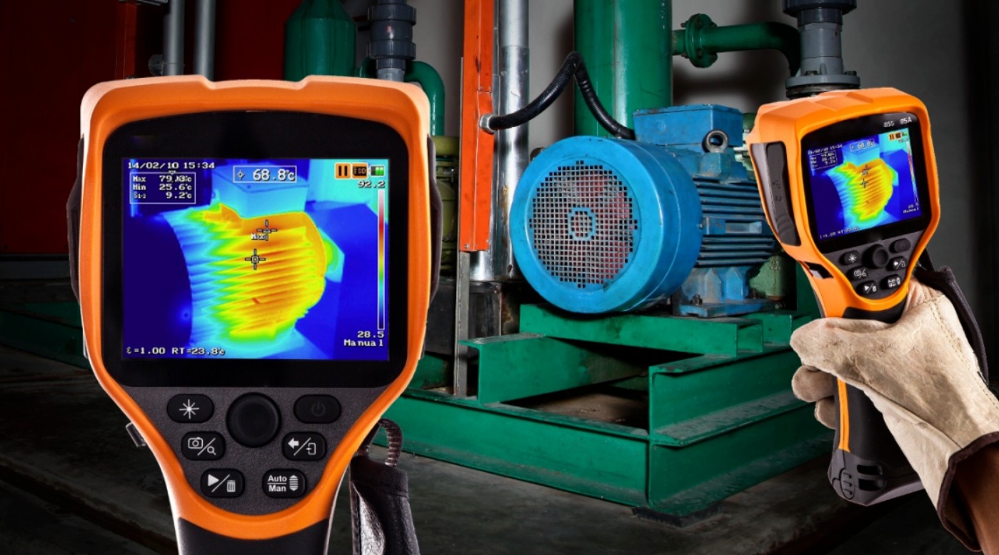
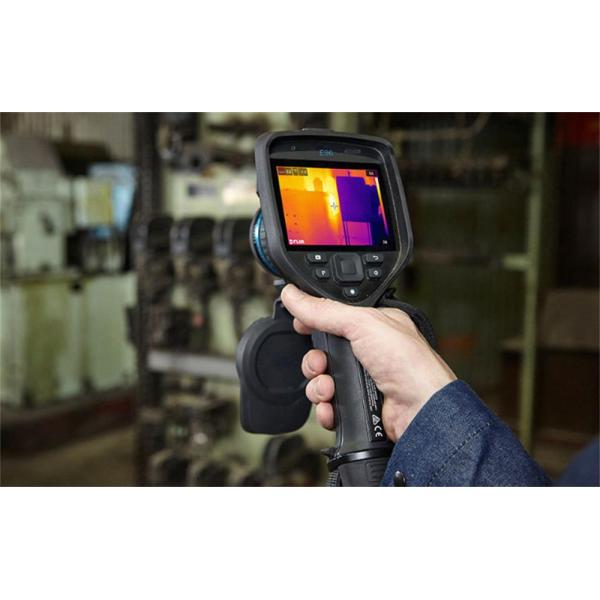
Thermal imagers and video cameras are best for troubleshooting equipment issues while the equipment is running. Electrical equipment must be at least 40% of the nominal load to detect problems - although maximum load conditions are ideal, if possible. This includes motors, drives, and their associated electrical connections, wiring, fuses, and transformers. The thermal image shows the surface temperature of these various components and allows the user to determine the best next steps, which may include further analysis, repair, or replacement.
In most cases, when using thermal imaging, you are looking for hot spots in your equipment, which is why it is critical that your equipment run to at least 40% of its nominal load. While thermal imaging can indeed provide immediate information about faulty equipment, it can also be used to build thermal maps.
Motor
Start by building a thermal profile of the motor - these are just high-quality thermal images of the motor running under normal operating conditions. This gives you a baseline of temperature measurements that you can use if something goes wrong with your device. Thermal images should include all critical components such as motors, couplings, motor and shaft bearings, and gearboxes.
When checking low-load conditions, be sure to pay attention to all possible problems, even if they reflect only small temperature differences. As the load increases, so does the temperature, and if there is a problem, expect a higher temperature difference with the load. All motors should have their normal operating temperature listed on the nameplate. Abnormal temperatures seen on a thermography inspection may indicate inadequate cooling, power quality issues, impending bearing failure, insulation failure, and/or shaft misalignment.
Three-phase Unbalance
Capture thermal images of all electrical panels and other high-load connection points such as drives, disconnects, controls, etc. Follow the circuit wherever you notice higher temperatures, and check the associated branches and loads.
Compare all three phases side by side and check for temperature differences. A circuit or branch that is cooler than normal may indicate a component failure. Heavier-loaded phases will appear warmer. Thermal conductors may be undersized or overloaded. However, load imbalances, overloads, poor connections, and harmonics can all produce similar patterns, so follow up with electrical or power quality measurements to diagnose the problem.
Connections and Wiring
Look for connections that run hotter than other similar connections under similar loads. This could indicate a loose, tight, or corroded connection with increased resistance. Hot spots associated with connections are usually (but not always) hottest at the point of resistance and get cooler with distance from that point.
In some cases, cold component anomalies are caused by the shunting of current from high-resistance connections. You may also find broken or undersized wires or defective insulation. NETA (International Electrical Testing Association) guidelines state that when the temperature difference (DT) between similar components under similar load exceeds 15 ℃ (~25 ℉), repair should be performed immediately.
Fuse
If the fuse shows hot on the thermal scan, it is probably at or near its current capacity. However, not all issues are hot-button issues. For example, a blown fuse can produce a lower-than-normal temperature.
Motor Control Center (MCC)
To evaluate an MCC under load, open each component and compare the relative temperatures of key components: busbars, controllers, starters, contactors, relays, fuses, circuit breakers, disconnects, feeders, and transformers. Use the guidelines provided earlier in this article to check connections and fuses and identify phase imbalances.
TIP: Measure the load at each scan so that you can properly evaluate your measurements against normal operating conditions.
Transformer
For oil-filled transformers, use a thermal imaging camera to view high and low-voltage external bushing connections, cooling ducts, cooling fans and pumps, and critical transformer surfaces. (The coil temperature of a dry-type transformer is much higher than the ambient temperature, so it is difficult to detect the problem with thermal imaging.) Combined with the previous guidance for connections and imbalances.
The cooling tube should look warm. If one or more tubes are relatively cold, oil flow may be restricted. Remember, like a motor, a transformer has a minimum operating temperature, which represents the maximum allowable temperature rise above ambient (typically 40 degrees Celsius). Exceeding 10 degrees Celsius above the nameplate operating temperature may reduce the life of the transformer by 50%.
The above 6 methods for troubleshooting using thermal imaging are introduced, if you want to buy a thermal imaging camera, please contact us.
JAVOL is a professional custom infrared thermal imaging cameras manufacturer. Relying on the multi-spectral high-sensitivity photoelectric sensor chip of advanced compound semiconductor materials, with the deep learning AI algorithm as the engine, it integrates low-light night vision technology, infrared thermal imaging technology, short-wave infrared technology, Multi-spectral technology in one fusion technology, our company designs, develops and manufactures advanced imaging products and system solutions, which are widely used in machine vision, automatic driving, drone payloads, high-end manufacturing, medical diagnosis and other fields.
Handheld infrared thermal imaging camera is an industrial temperature measuring device based on the principle of thermal image

